Tuesday, July 8, 2014

MPLS L3 VPN provisioning over IOS, JUNOS & VRP (Huawei) based PEs

Scenario:

This topology elaborates MPLS L3 VPN provisioning using Cisco's IOS, Juniper's Junos & Huawei's VRP (Versatile Routing Platform Software) based PE routers using different PE-CE routing protocols. 

·   The ISP’s core is using ISIS as IGP.
·   MPLS (LDP) runs on top of ISIS.
·   The RR JUNOS router is functioning as Route Reflector for Junos-PE, IOS-PE & VRP-PE.
·   The three PEs have MP-BGP relation with RR JUNOS.
·   The client has 3 sites running different platforms, i.e., IOS-CE, JUNOS-CE, VRP-CE.
·   PE-CE protocol between JUNOS-PE and IOS-CE is OSPF.
·   PE-CE protocol between IOS-PE and JUNOS-CE is eBGP.
·   PE-CE protocol between VRP-PE & VRP-CE is ISIS.

Platforms used in this topology are:

IOS-PE = Cisco IOS Software, 3600 Software (C3640-JK9O3S-M), Version 12.4(16a) running in GNS3

IOS-CE = Cisco IOS Software, 2600 Software (C2691-ADVENTERPRISEK9-M), Version 12.4(5a) running in GNS3

All JUNOS routers= Model: olive, JUNOS Base OS Software Suite [12.1R1.9] running in GNS3

VRP-PE =  Huawei Versatile Routing Platform Software VRP (R) software, Version 5.120 (AR2200 V200R003C01SPC900) running on Huawei AR2220 Router

VRP-CE = Huawei Versatile Routing Platform Software. Software Version : USG2110 00R001C00SPCa00 (VRP (R) Software, Version 5.30) running on Secospace USG2110-F-W

Configuration Files & Routing Tables:

Friday, April 25, 2014

QinQ and Link Aggregation over EX-4200

Scenario:
  • Two EX-4200 switches are connected back to back over ge-0/0/12 & ge-0/0/13 interfaces.
  • Both the above mentioned interfaces are part of Aggregated Ethernet interfaces called ae0.
  • ae0.0 interfaces are configured in Trunk mode with VLANs 12 (DATA) & 24 (qinq).
  • QinQ has been configured over ge-0/0/24 interfaces & these interfaces are in Access mode.
  • Two Cisco C851 routers are connected with ge-0/0/24 interfaces of EX-4200s.
  • Fa4 interfaces of Cisco 851 are configured with two tagged sub-interfaces.
  • Interfaces ge-0/0/10 are configured with VLAN 12 (DATA) in access mode and laptops have been connected to them.


Configuration Details:

Monday, January 20, 2014

MPLS L3 VPN provisioning over Junos & IOS based PEs

Scenario:

This topology elaborates MPLS L3 VPN provisioning over IOS & Junos based PE routers using different PE-CE protocols. 


·  The ISP’s core is using ISIS as IGP.
·   MPLS (LDP) runs on top of ISIS.
·   The CORE router is functioning as Route Reflector for Junos_PE, Junos_PE2      & IOS_PE.
·    The three PEs have MP-BGP relation with CORE (RR).
·    The client has 3 sites, CE1, CE2 & CE3.
·    PE-CE protocol between IOS_PE & CE1 is non-dynamic i.e., static routing.
·    PE-CE protocol between Junos_PE & CE2 is eBGP.
·    PE-CE protocol between Junos_PE2 & CE3 is OSPF.


    Network Diagram:


Configuration Details:

Sunday, September 1, 2013

Inter Provider L3 VPN -- Option B

Inter Provider VPN connectivity is often translated as International VPN which are normally required by multinational enterprises. This lab follows the second most scalable Inter-Provider L3 VPN Solution called “External Multiprotocol BGP” method.
Gear Used:

GNS3 (Intel Core i3 3110M with 4 GB  RAM)
Cisco C3640-JK9O3S-M, Version 12.4(16a), used for Provider & Provider Edge Routers (PE-A, PE-B, CORE-A, CORE-B, ASBR-PE-A & ASBR-PE-B)

C2691-ADVENTERPRISEK9-M, Version 12.4(5a), used for Client End Routers (CE-1, CE-2)
NOTE: Live IP Addresses & AS numbers used in this lab are purely fictitious; any resemblance to any IP/AS living or dead is purely coincidental.

Network Diagram:

 Scenario Detail:
We have 2 sites of a client CE-1 & CE-2 in need of VPN connectivity between each other located at geographically distant locations. Client couldn’t find a single ISPs presence at both locations. So, the VPN circuit has to be established across two ISPs. What follows is the complete configuration detail.

Configuration Files:

Monday, August 26, 2013

MPLS L2 Martini Circuits (Ethernet over MPLS)


Lab 1-A: Port Based MPLS L2 Martini Circuit

This time I’m going to configure MPLS based L2 circuit called ‘Martini’. Obviously, you can Google the term for theory.

ISPs utilize this technique to provide their customers with clear L2 circuits on an MPLS infrastructure. Let’s see how it is done.

Gear Used:

GNS3 (Intel Core i3 3110M with 4 GB  RAM)

Cisco C3640-JK9O3S-M, Version 12.4(16a), used for Provider Routers (P1 & P2)

C3725-ADVENTERPRISEK9-M, Version 12.4(15)T5, used for Provider Edge Routers (PE_A & PE_B)

C2691-ADVENTERPRISEK9-M, Version 12.4(5a), used for Client End Routers (Client_A1 & Client_A2)
Network Diagram:


Scenario Detail:
·         Client ‘A’ asked the ISP for a clear L2 circuit between their sites A1 & A2.
·         ISP’s infrastructure is based on MPLS.
·         So, the ISP has configured an MPLS L2 Martini circuit between its edge routers.
·         The diagram above has all the IP details.
·         Client has established its L3 network over this L2 link & is running OSPF.
 
Lab 1-B: Port Based MPLS L2 Martini Circuit
This lab implementation demonstrates that how client has used this port based MPLS L2 circuit to pass on multiple VLANs.
Gear Used:
GNS3 (Intel Core i3 3110M with 4 GB  RAM)
Cisco C3640-JK9O3S-M, Version 12.4(16a), used for Provider Routers (P1 & P2)
C3725-ADVENTERPRISEK9-M, Version 12.4(15)T5, used for Provider Edge Routers (PE_A & PE_B)
C2691-ADVENTERPRISEK9-M, Version 12.4(5a), used for Client End Routers (Client_A1 & Client_A2)
Network Diagram:


 Scenario Detail:
·         Client ‘A’ asked the ISP for a clear L2 circuit between their sites A1 & A2.
·         ISP’s infrastructure is based on MPLS.
·         So, the ISP has configured an MPLS L2 Martini circuit between its edge routers.
·         The diagram above has all the IP details.
·         Client is using this circuit to pass on multiple VLANs from site A1 to A2 & is running OSPF & EIGRP.
Lab 2: VLAN Based MPLS L2 Martini Circuit (with VLAN Override)
In real world, no ISP can spare a physical port of any of its routers for any client. Clients are directly connected with the ISP’s L2/L3 switches.
In this lab, I’m going to demonstrate that how VLAN based Martinis are created for multiple clients. Also, I’m going to show you how to configure a Martini circuit with different VLANs at both ends.
Gear Used:
GNS3 (Intel Core i3 3110M with 4 GB  RAM)
Cisco C3640-JK9O3S-M, Version 12.4(16a), used for Provider Routers (P1 & P2)
C3725-ADVENTERPRISEK9-M, Version 12.4(15)T5, used for Provider Edge Routers (PE_A & PE_B)
C2691-ADVENTERPRISEK9-M, Version 12.4(5a), used for Client End Routers (Client_A1, Client_A2, Client_B1 & Client_B2)
GNS3’s default Ethernet Switch
Network Diagram:


Scenario Detail:
·         Client ‘A’ asked the ISP for a clear L2 circuit between their sites A1 & A2 while client B wants an L2 circuit between B1 & B2.
·         ISP’s infrastructure is based on MPLS.
·         So, the ISP has configured two MPLS L2 Martini circuits between its edge routers.
·         The diagram above has all the IP details.
·         Client A has established its L3 network over this L2 link & is running OSPF while client B has established its L3 network over this L2 link & is running EIGRP.
·         For Client A, we have used VLAN 10 at both ends but for Client B, we have used VLAN 20 between PE_A & PE_SW_A and VLAN 30 between PE_B & PE_SW_B.

Configuration Files:
Lab-1
Lab-2
 

Wednesday, July 31, 2013

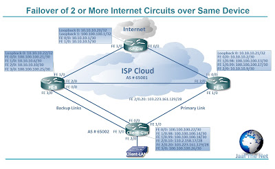
Failover of 2 or More Internet Circuits on Same Device

The rationale behind this design was that the client required an auto failover solution from the ISP. The ISP is provisioning client with 4 Internet circuits over same physical Ethernet medium via separate VLANs. Two out of these four circuits have radio links as backups & traffic shifting mechanism is manual. Client was terminating all of these circuits on same router of theirs & had PBR applied along with IP SLA (obviously, default route can’t be the option in case of multiple Internet links). 

At ISP side, PBR & IP SLA couldn’t be applied as the PE router was not the same for both primary & backup media. So, I used multiple techniques to fulfill client’s requirement keeping in view the ISP’s design too.
I used IP SLA & PBR at client end to failover between primary & secondary links so that traffic destined for Internet could take the appropriate path out. BGP was configured between ISP & Client device so that return traffic could take the appropriate path (same as outgoing) into client’s device.

Gear Used:
GNS3 (Intel Core i3 3110M with 4 GB  RAM)
Cisco C3640-JK9O3S-M, Version 12.4(16a)


NOTE: Live IPs used in this implementation are purely fictitious; any resemblance to any IP living or dead is purely coincidental.

Network Diagram:

Scenario Detail:
  • ·         Client has been assigned two 110.2.158.16/28 & 103.223.161.128/28 live IP pools by the ISP for the two separate links.  
  • ·         The 2 Internet links have been separated by VLANs 98 & 99 over the Primary media.
  • ·         Backup links are physically separate & are connected to different Ethernet ports of client’s router.
  • ·         BGP neighbor ship has been established over all four point to point connections.
  • ·         MED has been configured higher on backup links so that return traffic will follow the backup path in case of primary media outage.
  • ·         Route maps have been applied at ISP side on all neighbors so that any given link allows only the traffic of assigned subnet.
  • ·         At client end, PBR has been applied along with IP SLA tracking.
  • ·         Traffic from subnet 110.2.158.16/28 will route to 100.100.100.13 & in case this hop becomes unavailable, then, the traffic will route to backup next hop 100.100.100.21.
  • ·         Traffic from subnet 103.223.161.128/28 will route to 100.100.100.17 & in case this hop becomes unavailable, then, the traffic will route to backup next hop 100.100.100.25.
  • ·         The above two rules will also apply to return traffic.
    Configuration Files:

Wednesday, July 24, 2013

GRE Tunnel between Hub & Spoke with BGP Failover at Spoke Site

This is one small topology that I am going to put in production in few days. Below given is the In-House implementation.

There’s this one client & they are in need of a 10 Mbps VPN circuit between their H.O. & a new spoke site with in the same city. Two Metro Fiber circuits with Ethernet hand off are going to be deployed at the spoke site while the H.O. is already connected with the ISP over Metro Fiber. Both offices are going to be connected to the same PE router of the ISP.
BGP failover is required at the spoke site & Juniper SSG5 is going to be used for the purpose. The client will by-pass the ISP hops via configuring GRE Tunnel between their 2 offices.

Gear Used:
CLIENT-HO --> Cisco 851
ISP-PE --> Juniper SSG5
Client-Spoke --> Juniper SSG5 (To use it as a router, configured all interfaces in same zone)

Network Diagram:


Configuration Files: