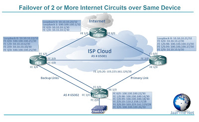
The rationale behind this design was that the client required an auto failover solution from the ISP. The ISP is provisioning client with 4 Internet circuits over same physical Ethernet medium via separate VLANs. Two out of these four circuits have radio links as backups & traffic shifting mechanism is manual. Client was terminating all of these circuits on same router of theirs & had PBR applied along with IP SLA (obviously, default route can’t be the option in case of multiple Internet links).
At ISP side, PBR & IP SLA couldn’t be applied as the PE router was not the same for both primary & backup media. So, I used multiple techniques to fulfill client’s requirement keeping in view the ISP’s design too.
I used IP SLA & PBR at client end to failover between primary & secondary links so that traffic destined for Internet could take the appropriate path out. BGP was configured between ISP & Client device so that return traffic could take the appropriate path (same as outgoing) into client’s device.
Gear Used:
GNS3 (Intel Core i3 3110M with 4 GB RAM)
Cisco C3640-JK9O3S-M, Version 12.4(16a)
NOTE: Live IPs used in this implementation are purely fictitious; any resemblance to any IP living or dead is purely coincidental.
Network Diagram:
Scenario Detail:
- · Client has been assigned two 110.2.158.16/28 & 103.223.161.128/28 live IP pools by the ISP for the two separate links.
- · The 2 Internet links have been separated by VLANs 98 & 99 over the Primary media.
- · Backup links are physically separate & are connected to different Ethernet ports of client’s router.
- · BGP neighbor ship has been established over all four point to point connections.
- · MED has been configured higher on backup links so that return traffic will follow the backup path in case of primary media outage.
- · Route maps have been applied at ISP side on all neighbors so that any given link allows only the traffic of assigned subnet.
- · At client end, PBR has been applied along with IP SLA tracking.
- · Traffic from subnet 110.2.158.16/28 will route to 100.100.100.13 & in case this hop becomes unavailable, then, the traffic will route to backup next hop 100.100.100.21.
- · Traffic from subnet 103.223.161.128/28 will route to 100.100.100.17 & in case this hop becomes unavailable, then, the traffic will route to backup next hop 100.100.100.25.
- · The above two rules will also apply to return traffic.
Configuration Files:

